What are Binocular Telescopes?
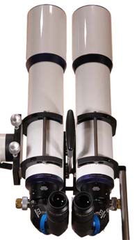
Binocular telescopes are observing devices consisting of two astronomical telescopes for both-eye observations.
It can be said that they are kinds of binoculars, but generally binocular telescopes need a mounting, and the eyepieces are changeable (magnifications can be changed.)
Telescope Types used for Binocular Telescopes
Some types of telescopes are used for binocular telescopes as followings:
[Refractor] The most suitable for binocular telescopes. With the use of EZM's, commercially available OTA's can be used for binocular telescopes as they are. With no central obstructions, clear images can be obtained even at very low powers. BinoTechno is a manufacturer specialized in refractor binocular telescopes.
[Newtonian]Though it's easy to get large apertures, the adjustments are rather delicate because there are multiple alignment elements. When using mass-market OTA's, some kinds of barlow lenses are necessary to extend the focal point. Besides, the visual images are mirror-reversed because of the odd times of reflections. If the major purpose is the planetary observations with high powers, a combination of a single OTA and a binocular viewer is more recommended.
[Schmidt-Cassegrain / Maksutov-Cassegrain] It's easy to get large aperture, and, with the use of EZM's, most models on the market can be used for binocular telescopes as they are. However, because of the slower f-ratio, they are not so suitable for low-power and wide-angle deep-sky observations.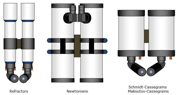
Component Parts of Binocular Telescopes
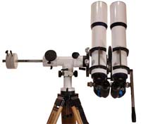
Binocular refractors consist of the following parts:
- EZM's (Erecting Zenith Mirrors)
- Optical Tube Assemblies
- Tube Joint Mechanism
- Interpupillary Distance Adjusting Mechanism
- Mounting
- Tripod
Hereunder, the detailed explanation for each part follows.
Functions & Principles of EZM
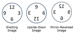 EZM (Erecting Zenith Mirror) is the essential part for binocular telescopes, with 3 important functions.
The first is "180-degree image rotation". The image seen through a refractor is upside-down, and EZM will rotate it 180-degrees again to yield an erecting image.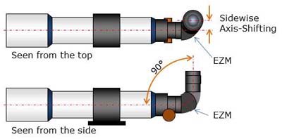 The second is "90-degree conversion of viewing angle". This is especially necessary to observe the astronomical objects high in the sky. Of course normal diagonal mirrors and diagonal prisms have the same function, but the images are mirror-reversed.
The third is "sidewise axis-shifting". The interpupillary distances of adults are mostly between 60mm - 70mm. Without this function, no larger diameter refractors than these figures could be used for binocular telescopes. Thanks to this function, larger aperture binocular telescopes can be manufactured.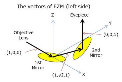 EZM realizes these 3 functions with only 2 flat mirrors, aligned in specific angles against the light path from the objective lens. To explain this concretely, let 2 mirrors set in the following vectors:
Premise: a telescope is on horizontal position / the original light path from the objective lens is X-axis / the horizontally diagonal direction against X-axis is Y-axis / the vertically diagonal direction against X-axis is Z-axis
The vector from the objective lens to the 1st mirror = (1,0,0)
The vector from the 1st mirror to the 2nd mirror = (1,square root of 2,1)
The vector from the 2nd mirror to the eyepiece = (0,0,1)
*This optical design was invented by Mr. T. Matsumoto in early 1980's.
Component Parts of EZM
EZM consists of the following parts:
- Nosepiece (a 2" O.D. barrel to be inserted into the telescope focuser)
- 1st Mirror Housing Unit (a triangle-shaped component on the telescope side, with a mirror on the bottom inside)
- Middle Ring (the sidewise axis-sifting amount can be determined with the thickness of this ring)
- 2nd Mirror Housing Unit (a triangle-shaped component on the eyepiece side, with a mirror on the bottom inside)
- Eyepiece Holder (a 2" I.D. barrel to accept eyepieces)
The distance from the rear end of the nosepiece to the upper end of the eyepiece holder is called "(optical) light path length". To reach the focus to infinity, the backfocus amount of the telescope must be longer than this length.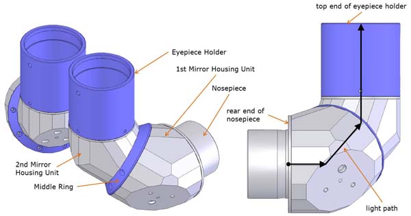
Alignment Elements of EZM
To realize the light path vectors mentioned above, the following alignment elements are necessary for the component parts of AZM:
- Vertical Angle of each mirror housing unit = 60-degrees
- Incidence/Reflection Angle of each mirror = 60-degrees
(*Reference: the incidence/reflection angle of a normal diagonal mirror is 45-degrees)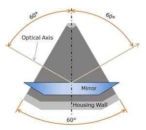
- Torsion Angle between 1st & 2nd mirror housing units = ARCCOS(1/3)=70.53-degrees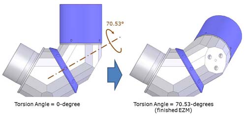
Precise "180-degree image rotation" and "90-degree conversion of viewing angle" can't be obtained if any of these elements is misaligned.
X-Y Adjusting Screws of EZM
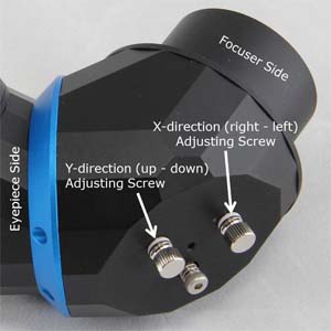 X-Y adjusting screws are equipped on the bottom of the 1st mirror housing unit of the right EZM. These screws are used to merge the left and right images when seeing through binocular telescopes with both eyes. By turning the X-side screw, the image in the right side moves in X-directions (right - left), and, with the Y-side, it moves in Y-directions (up - down).
However, these screws are not intended to correct the angular errors of the alignment elements mentioned above. They are for correcting the subtle individual differences of the observers and for compensating the centering errors between EZM's and eyepieces.
As the positions of the human eyes are not symmetrical but more or less asymmetric, the best point where the left and right images merged differs depending on each observer, same as the best focused point differs for each. This difference can be adjusted with these screws.
Precicely speaking, using these screws may cause the above mentioned alignment elements to be misaligned. But, as long as the adjustment amount is minimum (within 1/3 rotation of each screw), it won't give any practical effects on "180-degree image rotation".
When making binocular telescopes using our EZM's for yourself, if both the images do not merge unless these adjustment screws are rotated more than a half turn, you had better re-check other alignment elements (e.g. the parallelism of both the scopes, bending of the focusers, etc.) before doubting about the internal errors of our EZM.
Also, as you will notice when you actually operate these screws with looking through binocular telescopes, both the images are "suddenly" merged when they come closer to the certain range. This is due to the human brain's work. While it allows some misalignments, it makes the precise adjustment difficult.
Matching the Rotary Angles of the Fields of View
If any of the alignment elements of EZM or the parallelism of both the scopes is misaligned, even if the central images are overlapped by operating the adjusting screws, the rotary angles of the fields of view do not coincide with each other, resulting in unpleasant vision.
It's easier to notice this discordance when viewing terrestrial objects, especially horizontal or vertical structures in daytime, rather than viewing the stars. Sensitive observers seem to find it even with a 0.5-degree gap.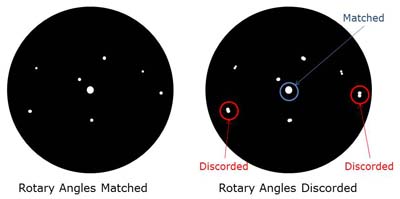 This discordance can't be corrected with the X-Y adjusting screws. If it occurs with your self-made EZM binocular telescopes, you had better re-check the alignment elements of EZM, the parallelism of both the scopes, and bending of the focusers.
Especially, it's the torsion angle of the 1st & 2nd mirror housing units that affects this field rotation. The error amount of this torsion angle is nearly equal to that of the rotary angle of the field. That is, when the error amount of the torsion angle is 0.5-degrees, the rotary angle of the field also becomes 179.5-degrees or 180.5-degrees. If the diameter of the middle ring between the 1st & 2nd mirror housing units is 60mm, 0.5-degrees correspond to 0.26mm on the circumference of this ring - you will find it's quite delicate.
The parallelism error of both the scopes and bending of the focusers also affect the field rotation. In a state that either of these problems exists, the discordance of the rotary angles always remains even if operating the adjusting screws to force the central images to be overlapped.
Points to be Noted in Choosing the OTA's for Binocular Telescopes
It should be the prime concern for every observer which telescopes to be chosen for making binocular telescopes. Needless to say about the optical performance, the following points are also very essential:
[Rigidity of the Focuser] EZM is relatively heavy and the eyepiece position is offset from the axial center of the telescope, so sufficient deflection rigidity and torsional rigidity are required for the focuser.
[Backfocus Amount] The maximum backfocus amount should be 10mm or longer than the light path length of EZM. There are not so many mass-market scopes with the adequate back focus amounts.
[Maximum Diameter] The necessary light path length of EZM is determined by the maximum diameter of the telescope tube (including the dewcap), so smaller diameter is preferable. Refractors with triplet objective lenses are mostly with larger diameters and therefore the backfocus amounts are often insufficient.
[Tube Roundness] Recent telescopes are mostly free from this problem, but some tubes of older scopes are made of rolled sheet metal. As it's difficult to set such scopes in parallel precisely, they are not suitable for binocular telescopes.
Tube-Connecting Mechanism
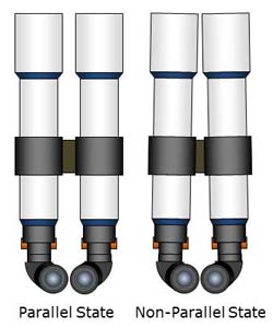 The most important function for the tube-connecting mechanism is to keep both the telescopes in exact parallel. As mentioned above, it's impossible for AZM to compensate the non-parallelism caused with the tube-connecting mechanism.
For self-made binocular telescopes, using the original tube rings to fix the telescopes is not always recommended, as the positioning errors and the diameter margins of the unloaded holes are often too large. For example, popular tube rings are designed to be fixed with two M8 bolts with 35mm distance. As the unloaded hole to accept an M8 bolt is approximately 9mm dia., it can tilt up to 1.6-degrees horizontally. Furthermore, if the opposite telescope tilts with the same amount in a counter direction, it becomes 3.2-degrees of non-parallel setting totally. Of course this might be an extreme example, but anyway it's necessary to try best to maintain a precise parallel state as possible.
Interpupillary Distance Adjusting Mechanism
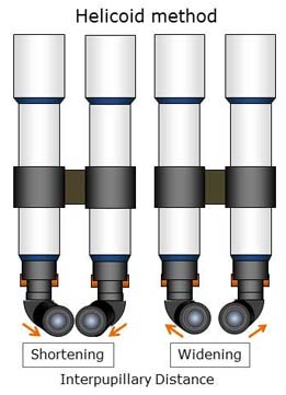
As the interpupillary distance varies depending on each person, binocular telescopes must have a mechanism to adjust it. There are 2 methods as followings:
[Tube Sliding Method] A method to equip a function to slide the telescope tubes sideways with the tube-connecting mechanism for adjusting the interpupillary distance. It's suitable for not so heavy small to medium aperture (up to 130mm) scopes. This method always requires rigidity and precision to keep the both tubes in parallel. In this method, the focus point is not changed when the interpupillary distance is changed, so it's easy even for beginners to handle.
[Helicoid method] A method to install a straight advance helicoid between EZM's 1st and 2nd mirror housing units for adjusting the interpupillary distance. The tube connecting mechanism can be simpler as the adjustment can be performed with these helicoid parts. However, the helicoid requires a certain degree of torsional rigidity and precision so that the torsion angle between the 1st & 2nd mirror housing units should always be kept constant. As changing the interpupillary distance will change the focus point, the observers have to get used to using this method.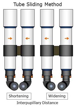
Mountings
As it's necessary for binocular telescopes to keep the whole unit always horizontal, altazimuth mounts are most suitable. If loaded onto equatorial mounts, some special mechanism to keep both the tubes horizontal in any aiming direction.
There is no specific mounting for binocular telescopes available on the market, still the followings should be suitable:
[Kasai Trading AZ-3 Altazimuth Mount] A simple T-shaped altazimuth mount. Suitable for high power observations thanks to the manual slow-motion controls on both axis.
[AOK AYO II] A sturdy T-shaped altazimuth mount. Encoders can be installed and Go-To function can be added.
[AOK AYOdigi II] A very sturdy T-shaped altazimuth mount with GO-TO function.
[iOptron AZ Mount Pro] A T-shaped altazimuth mount with Go-To function. Suitable for high power observations thanks to the automatic tracking function.
[Losmandy AZ8 Altazimuth Mount] A very sturdy single arm altazimuth mount with up to 15kg loadable capacity on one side.
[SkyWatcher AZ-EQ5GT] Convertible to an equatorial or an altazimuth mount. The altazimuth mount mode is suitable for binocular telescopes. Go-To and automatic tracking functions are equipped.
[Kenko/Tokina AZEQ6GT] A scale-up version of AZ-EQ5GT.
[Vixen HF2 Altazimuth Mount] A simple fork altazimuth mount loading up to 100mm aperture binocular telescopes. There are a lot of examples of use.
[Kokusai-Kouki Bulldog Altazimuth Mount]A sturdy fork altazimuth mount. Encoders can be installed and Go-To function can be added.
Tripods
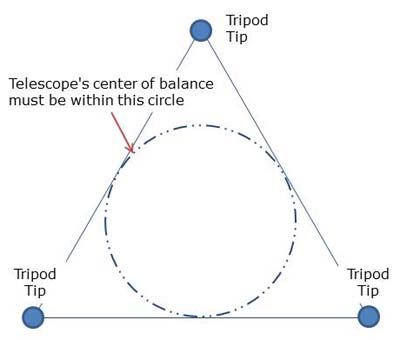 Same as for a normal astronomical telescope, a sturdy tripod should be chosen. In addition, for binocular telescopes, the installation radius should be well minded.
As the center of balance of binocular telescopes is often offset against the center of the tripod, there is a risk of tumbling if the installation radius is too small. Such a tripod of enough size should be chosen as the binocular telescopes' center of balance fits into the inscribed circle of the triangle drawn by the 3-leg tips.
Caution: Even if the above mentioned condition is fulfilled when the tripod is extended, the binocular telescopes' center of balance may get out of the circle when the tripod is retracted. Be especially careful when keeping the binocular telescopes on the tripod in retracted state.
Reflective Coatings
BinoTechno supplies the following 3 types of reflective coatings:
[Enhanced Aluminizing] Most generally-used reflective coating. Ours yields over 93% reflectivity on average throughout whole visual wavelength range, and over 95% within the highest responding wavelength range of the dark-adapted eyes (450nm - 550nm).
[Dielectric Coating] Different from normal metal coatings like aluminizing or Protective Silver Coating, it's a kind of "multi-layer" coating to yield highest-possible reflectivity. The coated surface is very hard, assuring semipermanent durability. Ours achieves over 99% reflectivity in Rs (S-polarized light) within 400nm - 700nm under 60-degree incident angle, and over 98% in Rp (P-polarized light) / Rave (average) within 400nm - 650nm. However. by the very nature of this special coating, the reflectivity falls keenly just outside the reflectable wavelength range.
[Protective Silver Coating] The top advantage of Protective Silver Coating is its high reflectivity of red light. Ours keeps over 97% reflectivity at around 700nm, while our enhanced aluminized mirror yields only 91%. However, as dark-adapted human eyes' response peaks at green light (around 500nm) and dramatically falls at red (longer wavelength) side, the visual differences compared to the other coatings are resultingly minimum. Yet, Protective Silver Coating is recommended to those serious astronomers who require "perfection".
References:
Reflectivity of Enhanced Aluminizing
Reflectivity of Dielectric Coating
Reflectivity of Protective Silver Coating
Responses of Human Eyes under Dark- and Bright-Adapted Conditions
Policy for Our Products
The users' adjusting range is always minimized in our products. The users should only adjust to compensate the personal differences, such as the interpupillary distance or the positons of the eyes. All the other elements are pre-adjusted precisely.
To realize this high standard, all the components' alignments are guaranteed with the machining accuracy. For example, both the mirror housing units of our EZM can't be connected except on the exact torsion angle of 70.53-degrees.
Such a structure that can't be adjusted afterward might be uneasy for some users, but we think differently: if it's adjustable, it means there is a possibility of future misalignments. Recent machine tools are capable of metal processing much more accurate than before. In the case of binocular telescopes using EZM's, as the target values of the alignments are clear, we believe it's more secure to ensure the alignment precision by metal processing and to provide the adjustment-free products.
This way of thinking comes from the experience of equipment design that we have engaged in for over 30 years. Facilities with many adjustable functions have difficulty in their starting up. And, once a trouble occurs afterward, there are many suspicious places and it takes a lot of time to recover it. Lessons learned through many experiences are "to ensure alignment precision with each component's accuracy if it can be achieved with itself" and "the only alignments that can't be achieved with the components' accuracy should be guaranteed by adjustment.".
And, when doing this "adjustment", we always take care of the followings:
[Fixing the Required Accuracy] The required accuracy of each alignment is determined from the overall target accuracy. For example, our target tolerance of the gap angle of the field rotation of our binocular telescopes is 0.5-degrees or less. As there are about 10 points to determine this total figure, the required accuracy on each point is set to within 0.05-degrees. (In practice, the discordant amount is not a simple addition of each accuracy variation figures - some of them cancel or compensate each other.)
[Using Measuring Equipment] For the concrete targets of required accuracy, we use the measuring instrument with higher sensitivity. For example, if the target is within 0.05-degrees, we use a measuring instrument which can distinguish within 0.01-degrees at least. (It's impossible to distinguish this accuracy with eyes alone.)
[Pre-Adjusting Every Adjustable Point] It's difficult to compensate the error of some adjustment points with the others. We will adjust every point to ensure the target accuracy.
[Distinguishing Between Adjustment and Confirmation] For example, when seeing through binocular telescopes, it is "confirmation", not "adjustment", to confirm the horizontal lines of the right and left fields of view are matched without field rotation. If they should not matched well, we do not simply adjust but reconfirm the accuracy of each alignment with a measuring instrument, etc.


